Creating Linkages
Basic Setup
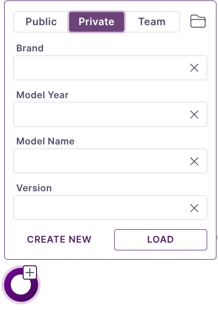
All bike parameters are modified through the left sidebar. While models can be created from scratch it is usually easier to base it on one of the many public database examples and modify as needed.
Adjust Critical Geometry
Under the Geometry tab the geo parameters can be set. Several of the parameters are required to set kinematic points.
Rear Center: Determines the horizontal position of the rear wheel at full extension. Major impact on all kinematics.
Front Center: Calculated from the bike geometry chart. Will only impact anti-squat and anti-rise results.
BB Drop: Positions the wheels vertically with respect to the coordinate system. Moderate impact on kinematic results.
Horz. BB Offset: Is the offset of the bottom bracket with respect to the Global coordinate system (GCS). Rear center is measured from this point impacting the final position of the rear wheel in the GCS.
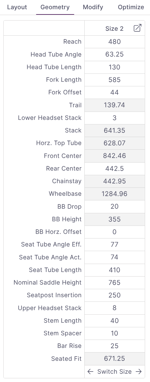
Note: The active size will always be shown in the sidebar and is used for the solve. Different sizes may have slightly different kinematics results due to small variations in geometry such as rear-center length.
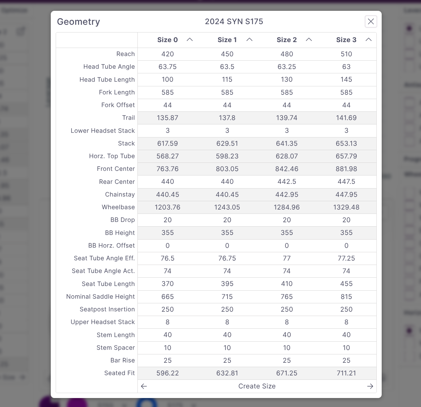
If you want to look at the differences between multiple sizes the expanded geometry chart can be opened using the expand icon in the top right.
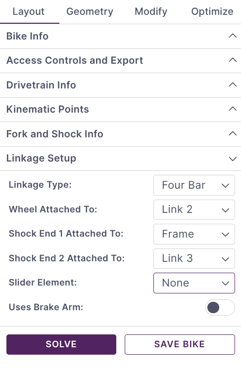
Setup Linkage Arrangement
Under the Linkage Setup heading of the Layout tab all the linkage configuration parameters can be adjusted.
The Linkage Type selector determines how many primary links will be in your system. This is not necessarily the same as the common terms for linkages like Single Pivot. In all cases the frame is counted as the final link.
Once the linkage type is selected the attachments can be made. Non-linkage components such as the shock, wheel, and idler can be attached to any member. When changing between linkage types double check all attachments are changed to ensure a valid solution.
Adjust Points
Kinematic points can be adjusted by setting values directly on the Kinematic Points heading of the Layout tab or using the graphical plot. To adjust points on the plot either drag the point directly or select the point by clicking it and use the arrow keys to shift the point. The currently selected point will be highlighted in light grey. The Q and W keys can be used to tab between the points when the plot is selected.
Component Selection
Under the Fork and Shock Info heading the shock stroke and actuation direction are set.
The shock length is controlled through several parameters. Shock Extension Length will normally show the difference between the specified shock length and the two kinematic points defining the ends of the shocks. Instead, it can often be convenient to set the shock length to fixed using the Fix Shock Length selector. This will allow you to adjust either the x or y coordinate at the end of the shock and have the other coordinate update to maintain the exact shock length specified. The shock extension length is set to fixed value in this case.
The Drivetrain Info heading contains the parameters used for calculating anti-squat. Idler pulleys can be enabled here with the Uses Idler selector.
Solving
Solving occurs as you make changes. If there is an unexpected error or issue you can re-trigger a manual solve by clicking Solve from the bottom of the Layout tab.
Advanced Model Creation
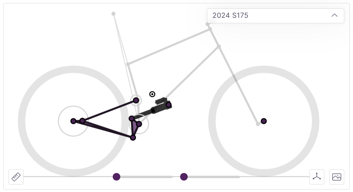
Model Linkage from an Image
To model a linkage from an image open the Image Overlay panel using the icon in the bottom right of the bike plot. An image can be uploaded or linked from a URL. Generally the chainstay length or shock length is a good reference for image scale. Once the image is scaled properly you can use the zoom and drag features to position points as accurately as possible.
Note: Many linkages are very sensitive to millimeter displacements. While a helpful tool for analyzing the general properties of a given layout, image mapping should not be used for reverse engineering purposes. In particular, any short link bikes (such as VPP, DW link, or hanging link horst) have a very high degree of sensitivity to point positions.
Optimization
The optimization engine will automatically move points to match a given set of target curves (leverage, anti-squat, and anti-rise). To run it:
Layout a basic linkage close to what you would like to end up with
Select which curves you would like to target (usually just leverage or leverage and anti-squat is enough).
Set your boundary conditions for how points can move. Often some points cannot move at all (such as main pivots) while others might have a large degree of freedom
Run the optimization!
Once the study is complete you can load the result and compare.
For detailed information see the documentation here.
Troubleshooting
syn uses a robust force-based solver with a large amount of flexibility. As a result there are many combinations of parameters that will not lead to a valid solution.
If you are not getting a solution check the following:
If you have recently changed the type of linkage (such as going from a 4 bar to a single pivot) ensure that all of the connections are on links that exist. Changing the linkage type will not move any connections on its own.
Ensure the shock is connected to at least one moving link. If the linkage looks correct but is not moving try changing the shock direction (push/pull). It may be that your configuration is driving the shock in the wrong direction.
Check for linkage lockouts. Moving the
Travel Slidersat the bottom will allow you to see where the links might end up reversing. Incorrect connections may cause lockout unintentionally.
Note: If the linkage locks up partially through the travel you will still get plotted curves until there is a lockout or shock reversal. Open the
Bike Infopanel by clicking on the bike's name to see how much shock travel was able to be used.